I2C LCD Configuration
These devices are commonly found as 16x2 I2C LCD Display and 20x4 I2C LCD Display. They typically use the PCF8574 or PCF8574AT I2C adapter board which converts parallel LCD interface to I2C.
Hardware Setup
- Connect your I2C LCD to the ESP device:
- SDA → GPIO21 (ESP32) or GPIO4/D2 (ESP8266)
- SCL → GPIO22 (ESP32) or GPIO5/D1 (ESP8266)
- VCC → 5V - VIN when connected to USB or external adapter. ESP devices use 3.3V otherwise. Won’t work if you’re using a battery.
- GND → GND
Software Configuration
- Enable the feature near the top of src/main.cpp:
#define INCLUDE_I2CLCD- Configure your LCD lower in src/main.cpp:
#define I2CLCD_size 1         // 0 = 20x4; 1=16x2
#define I2CLCD_ADDRESS 0x27   // or 0x30, 0x3F, etc.
#define I2CLCD_LIBRARY 1      // 0 = PCF8574AT; 1,PCF8574T (Check the chip behind your LCD adapter)
#define I2CLCD_TEST 0         // 0 = disable; 1 = enable showing "hello world" on startup
#define I2CLCD_SDA SDA        // define your i2c SDA pin here, it is set by default to the hardware pin (SDA is a constant that means that but you can use a number for your pin)
#define I2CLCD_SCL SCL        // define your i2c SCL pin here, it is set by default to the hardware pin (SCL is a constant that means that but you can use a number for your pin)
⚠️
If your LCD doesn’t work, you may need to find its I2C address:
- Use an I2C scanner sketch
- Common addresses are 0x27 and 0x3F
- Use I2CLCD_TEST to check if the device is working
SimHub capabilities
Verify that the Arduino tab shows the device with a feature I2C LCD: True.
SimHub will display the text shown in the Arduino -> Screens tab.
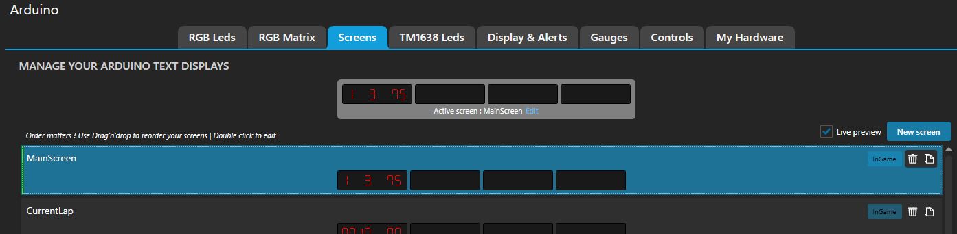
By default when a game is not running it displays the current date. When a game is running it displays [“Current Lap” “Gear” “Speed”] but you can edit the data, the order, etc in the editor.
